
Visit the whole site at: http://borg20011.tripod.com/borg_link_o_rama.htm
Page 13.
CONTENT:
1- All years R1 de-restriction 2- AIS removal (2 topics) 3- 02 airbox inlet modification
4- 00-01 tach cluster installation on a 98-99 5- How to read a dyno chart
6- Where to get switched current on a R1
![]()
1
How to de-restrict 98-01, 02-03 and 04 R1`s
AIS removal procedure and airbox inlet mod.
Here I will run you through the easy task of de-restricting your bikes.
This applies only to some European and Asians markets.
First thing first:
98-01 bikes:
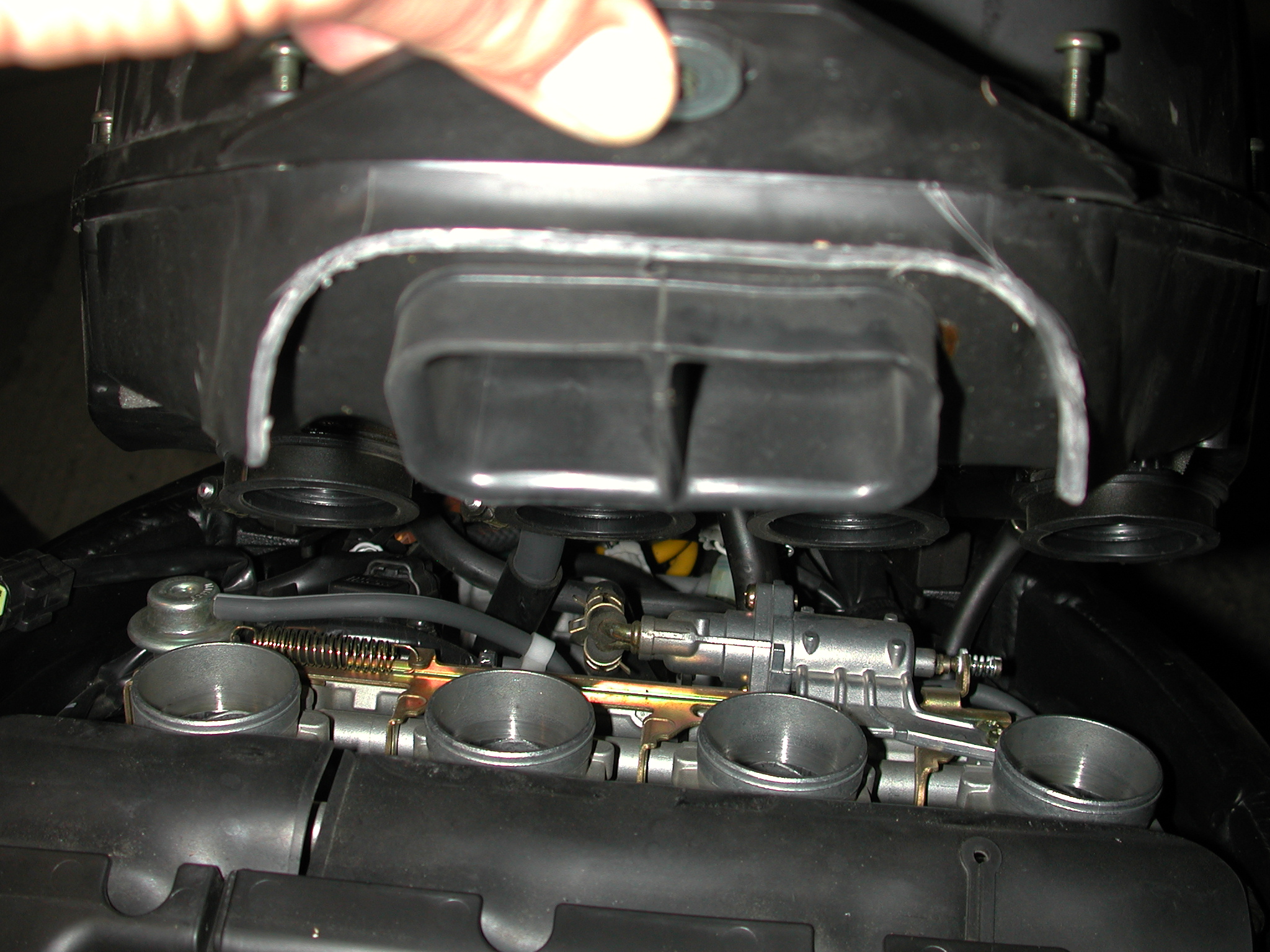
This is simple; all you got to do is remove the tank and remove the airbox to get to the carbs;
Now you can do it 2 different ways:
-By removing the carbs
-By simply removing the carbs tops
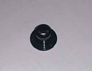
In either way, you should look for this device stuck/glued or just placed in the carbs tops (all 4):
That's it for the 98-01 bikes!
All those restrictors are doing is prevent your slides from opening fully.
![]()
Now the 02-03 bikes:
Do the same mod as the 98-01 bikes with this mod:
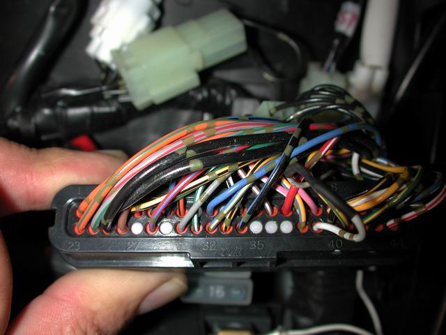
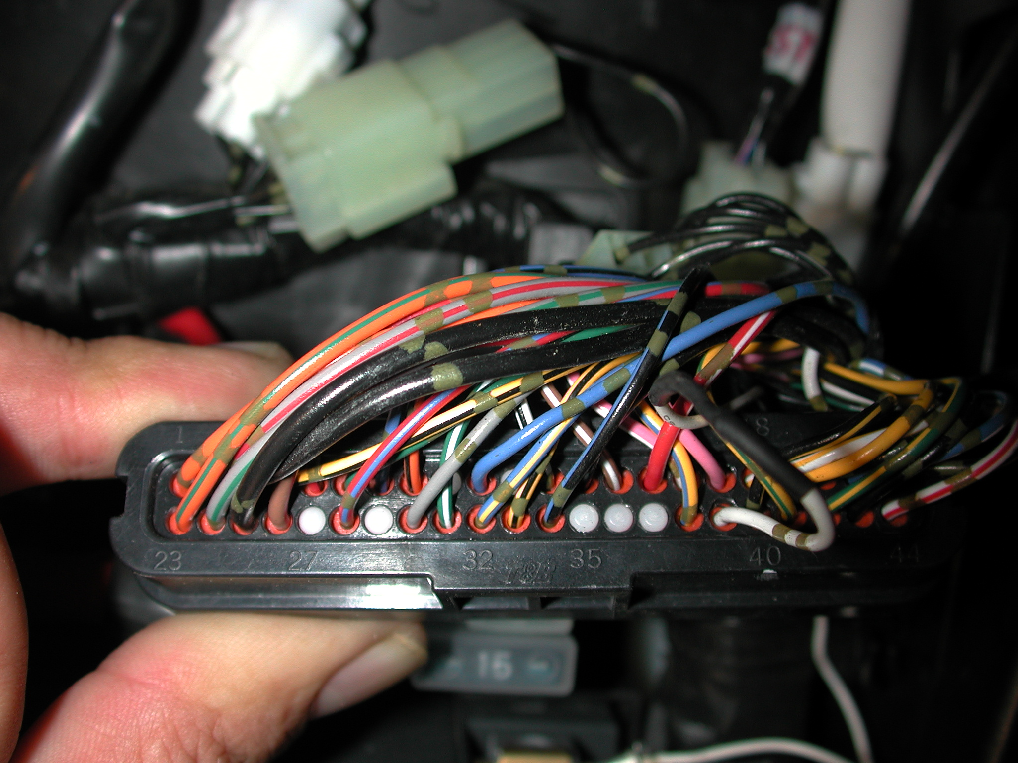
You got to cut a wire in the ECU main plug...it is white with 2 gold stripes on it.
Right now, this wire brings live power (+) to the ECU's restricting circuit; all you
have to do is cut it say, at about 2 inches from the connector (in case you need to go back to
restricted state) and solder a length of wire (same gauge) to connect it to the negative (-) post
of the battery.
SIMPLE!
Pics of the mod (in big and small format):
Location of the wire on the main ECU plug: Small pic Big pic
Wire mod location: Small pic BIG pic
Note: The object of doing this wire modification is to restore the fuel quantity delivery
to the same level as the models which are not restricted; it has to be done
with the throttle bodies slides restrictors removal.
Finally, the 04 models:
http://www.r1team.com/acc-yzfr1-768.htm
(It is in french, But I`ll work on a translation soon)
------------------------------------------------------------------------------------------------------
2
02 R1 AIS removal procedure.
(Air injection system, similar procedure for the 00-01 )
(Not finished, need pics of the airbox plumbing plugging)
By Throttle-cntrl (r1-forum member)
Here are some directions as to
how I did it. I have photos also if anyone needs them. This is for a 2002 model,
the 00-01 are a bit different, they have another hose that needs to be plugged
instead of wires (like the 02).
AIS REMOVAL (Air induction system)
The air induction system burns unburned exhaust gases by injecting fresh air
(secondary air) into the exhaust port, reducing the emission of hydrocarbons.
WHY WOULD YOU WANT TO REMOVE THE AIS ?
Approx 4lbs of weight savings (this is questionable, I did not weight it but
I would guess 2-3 lbs at most)
Convince of changing oil with out unbolting AIS or header
Get rid of the backfiring or popping
ITEMS TO BUY
Helicoil kit, 5/16 18. Found at the auto parts store.
Tube of the red hi-temp sealant. Found at the auto parts store.
Locktite Blue. Found at the auto parts store.
Four 5/16 18 Allen head bolts (about 3/4 long). Found at the hardware store.
3/8 or ½ inch diameter vacuum plug. Found at the auto parts store.
INSTRUCTIONS:
-Remove right and left side plastics and lowers.
-Remove radiator. I tried to leave this intact as long as possible, but found
it necessary to remove to provide plenty of working room in and around the heads.
This is your engine we are talking about here so take the time to do this right.
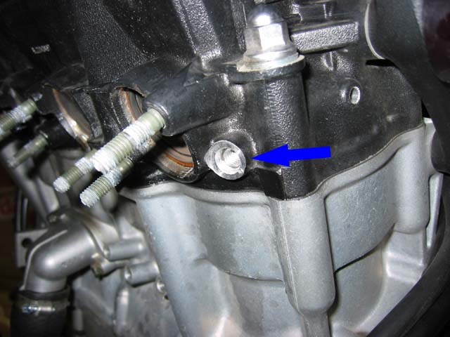
(TIP, there is a drain bolt found by the oil cooler on the front of the engine
block. It should be a copper bolt.) I drained the coolant into a bucket and
reused once I put it back together.
-Remove header/exhaust system
-Remove front seat
-Remove any steering dampers and prop up tank to allow access to the air box.
-Plug air box outlet using a 3/8 or ½ vacuum plug.
-Locate AIS and uninstall. Do not damage the bracket, you still need that to
stabilize the lower portion of the radiator. Trace the wire going to the AIS
solenoid, it runs back to the general area under the gas tank. Unplug it from
its harness. Apply electrical grease (found at a Radio Shack) to the end of
the connectors and shrink wrap the end of the harness so you can preserve it.
-Remove outlets to exhaust ports on the head. To do this will require a good
set of vice grips or pliers, lots of twisting and a squirt of WD-40. Once you
get these out the nerve-racking part of the mod begins.
-You now need to tap these holes. Get out your trusty Helicoil tap. The kit
is a 5/16 18 kit, this is different from a 5/16 18 tap. The purpose of a
Helicoil is to restore threads to a 5/16 diameter, thus requiring a larger
tap when you insert the coil they will act as your new threads.
I used a 3/8 drive ratchet and a 11/32 12 point socket to hold the end of
my tap. Line it up in the hole and drive the tap in clockwise. You want to load
up the tap with plenty of grease to catch the metal shavings created. Drive
the tap in a few turns, back it out and clean off the grease/shavings. Repeat
this step 3 or 4 times until you have created about ½ of threads deep in to
the head. You want the Helicoil to twist in just far enough that it is sunk
in nice and flush with the head.
-Now that you have created a nice clean set of threads for the Helicoil you
need to install the Helicoil. For this I used some of the orange hi-temp sealant
on the actual coil. I took the tool supplied with the kit or a set of long needle
nose pliers or long vice grips, clamped that to the tang of the coil and screwed
it in the head clockwise. This is the dangerous part of the mod. I dont think
anyone wants to drop the tang down in the head, so pay attention ! Take your
needle nose or vice grips and clamp it on the tang of that coil. Hold it good
and tight, twist back and fourth until it becomes week and breaks off. Pull
it out of the head, dont drop it ! I almost dropped one and about gave me a
heart attack ! I could only imagine bad things happening if that little piece
of metal were to fall into your heads.
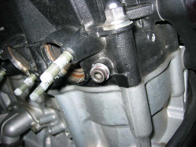
-Locate your four 5/16 18 Allen head bolts. Apply a coating of hi-temp sealant
or some Locktite. I dont know if the Locktite will help in this application
because of the extreme temps. Torque down the allen heads to 10 ft/lbs.
-Clean up access sealant and admire your work !
Pics of the procedure:
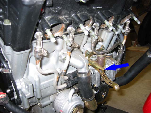
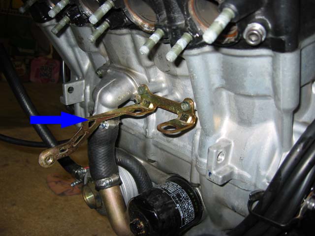
There are 2 ways of doing this (about the AIS in-head adaptors):
-You can remove them entirely, tap the holes and install a bolt: PIC PIC
Note: The size of the bolts and tap are mentioned in the text preceding this.
-You can tap the adaptors and insert bolts, but I heard that those may fall eventually (the adaptors).
Note: The size of the bolts
and tap needed for that is 10x1.25
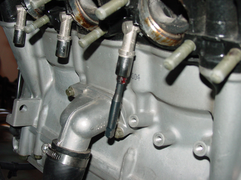
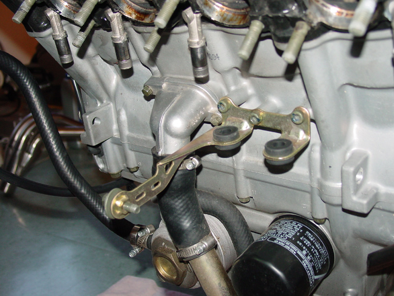
Radiator bracket with AIS: PIC
Radiator bracket installed back on the bike without AIS: PIC
ALSO:
Air induction removal procedure with pics!!!
http://www.stormriders.ca/HowTo/air_induction_removel.htm
![]()
3
02 inlet airbox modification.
Now those pics are very blurry...but you will get the idea.
The object of this mod is to try to let more air enter the box...
how will that affect your mappings is a mystery.
![]()
4
How to install a 00-01 tach cluster on a 98-99 by Sam Farris.
I worked with a gentlemen in
Hawaii on installing a 2000 gauge cluster into a '98' R1. Below is a culmination
of all our correspondence,....BTW, he did get it to work! :o)
Wayne,
This is the way I interpret what's going on.
1) The green/black wire coming from the 2000 dash is the 'fan relay activation
line'.
2) The green/yellow wire coming from the 1998 dash to the Igniter Unit is the
'bad fuel level sensor' wire.
3) From review of the specifications for the 1998~99 temperature sender and
the 2000, these sensors are totally electrically/functionally incompatible.
The 2000 sensor will not work with a 98~99 dash and a 2000 dash will not work
with a 1998~99 sensor. It appears that Yamaha decided to incorporate a speed
sensor tach diagnostic for model year 2000. This then 'pushed' the responsibility
of fuel level sensor diagnostic on to the dash. This action then 'frees-up'
a spot in the dash connector where the 'bad fuel level sensor' wire (green/yellow)
went. Yamaha then said 'If we use the temperature sender information for both
indication and fan control, and use this 'open slot' for 'fan relay activation',
we can save the cost of a thermo-switch, installation time, and some radiator
configuration work, all for the cost of one fan relay! As I see it, they saved
some money at the cost of some system redundancy in a 'safety critical' system.
By having a separate sender and switch, if one fails, you still have the other
to either indicate temperature trouble or control temperature. With this system,
if the sensor fails, you lose both. Not good in my mind (the bean counters will
always win a fight against lawyers in the corporate world).
Anyway, here is my recommendation Wayne.
1) Use the 2000 temperature sender. If the 1998 wire harness is not compatible
with the 2000 sender, modify the 98 harness (add mating connector for 2000 sender).
2) Use the 1998 temperature switch. This will of course plug right into the
1998 harness.
3) Snip the green/yellow wire on the bike 'main harness' side of the dash connector.
Connect one end of a 100 ohm resistor to snipped green/yellow wire coming from
the main bike harness and connect the other end to chassis ground.
***Sam***
Some more about this from Sam:
1) Use the 2000 temperature sender.
If the 1998 wire harness is not compatible
with the 2000 sender, modify the 98 harness (add mating connector for 2000 sender).
2) Use the 1998 temperature switch. This will of course plug right into the
1998 harness.
3) Snip the green/yellow wire on the bike 'main harness' side of the dash connector.
Connect one end of a 100 ohm resistor to snipped green/yellow wire coming from
the main
bike harness and connect the other end to chassis ground.
![]()
5
How to read a dyno chart.
This is fairly easy...learn it then impress your friends or don't let you impress by that obscure tuner anymore!
When you look at a Dyno chart:
- All gear runs -> test the main jets (upward sloping=lean; downward sloping=rich)
That means that looking at the far right part of the curve, right before it drops, if its tailing up, you are lean;
if its tailing down, you are rich.
- Correct jetting -> all gear run is 1-2hp higher than 4th gear run.
- Lean jetting -> 4th gear > all gear ,they are perfectly matched...but this
is not what you are looking for.
- Rich jetting -> All gear 3+hp
> than 4th gear; the opposite of the perfect jetting.
Ignition Advancers:
- Lean out the jetting (approx. 1 main jet size per 5-7* of advance).
Example: You got 132.5 mains in there, you need 5 degrees of advance, then you got to back to 130`s.
But then again, who will run 5-7 degrees of advance on their bikes?
The opposite is also true:
Richen jetting one main size if you want to run 4-6 degrees of retard.
Usually, this situation is found on big nitrous shots, 100hp shots and more (unlikely on our bikes)
since we run an additional big fuel pump and dual-outlet fuel petcock...not great when off nitrous.
![]()
6
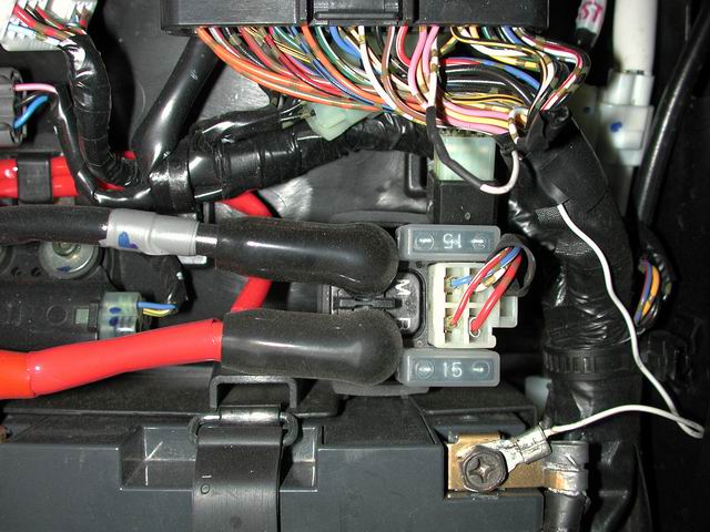
Where to get switched current on R1`s.
Tap into the brown/blue wire that feeds the fuse box under the seat.
As has been suggested, utilize
an in-line fuse.
By tapping into the brown/blue wire, the only time the detector will receive
power is when
the ignition key is turned on. This will prevent you accidentally leaving the detector
turned on and draining your battery.
Another source of switched power would be the blue wires on each sides of the bike in front, which feeds
the running lights in you turn signals; but this is a rather dirty power source which cant hold a high current drain
so keep small accessories for this if you need a closer-to-the-front source.