
Visit the whole site at: http://borg20011.tripod.com/borg_link_o_rama.htm
Page 10.
HOW TO TEST A RECTIFIER/REGULATOR
And install a cooling fan on it!
First, read this:
Sam's "what they do" on rectifier/regulators
It seems that the R1 has had more than its share of charging system problems. I am not sure if it is due to poor design, or due to owner neglect/ignorance. My guess its a combination of both. Before anybody sends me hate mail, I do not equate ignorance to stupidity. There are many things I am ignorant about, but I do not consider myself stupid. Anyway, there is not much I can do in regard to design, so I thought that I would gather my knowledge of what I have learned over the years and share it with everyone.
Charging System Overview
In a nutshell, the alternator generates AC electrical power from the energy of the spinning engine and supplies all of the electrical power needs of the system, which includes battery charging. The rectifier/regulator takes the AC electrical power generated by the alternator and converts it to DC. In addition, the rectifier/regulator keeps the electrical system voltage constant. The battery supplies current to the starter motor for engine starting or supplies current to the rest of the electrical system whenever the engine is not running. Whenever the engine is running, the battery should never be supplying current to the electrical system; only taking in current so as to maintain charge level.
Stator
The stator is the core of whats known, in this case/example, as a three-phase alternator. The stator, as the name implies, is a stationary coil of wire. More explicitly, for the R1 (and many other bikes, cars, etc.), it is actually three coils of wire with one end of each of the coils commonly connected together. Coils configured this way are known as a Y or a star configuration. Often, coils connected in this way are drawn schematically such that they resemble the letter Y, hence the name. With one leg of each stator coil commonly connected, this leaves three coil wires with connections yet to be defined. It is these three wires which are the output of the stator, and hence the output of the three-phase alternator.
As I said, the stator is the core of the three-phase alternator, but there is yet another piece to the puzzle; the rotor. As the name implies, the rotor rotates. The engine, of course, spins the rotor. The rotor physically encircle the stator coils. It is the spinning of the rotor that creates the current in the stator coils, which in turn flow the current to the rest of the electrical system. The reason the spinning rotor helps to create the electrical current is because the rotor is a permanent magnet (actually multiple permanent magnets). If you recall physics 101, one of the ways to create electrical current is to take a wire and a magnet and move one relative to the other, and a resulting current will be induced in the wire.
Those of you intimately familiar with automotive charging systems should, at this point, recognize the fundamental difference between a cars system and a bikes; there is no field coil (AKA electro-magnet) in the bike alternator, it is instead a permanent magnet. What this then means is that unlike the automotive system where the regulator controls field coil current, which in turn controls the strength of the magnetic field, which in turn controls the power output of the alternator, the bikes alternator is running at its maximum voltage output (dictated by engine speed) all the time.
As far as the mechanics of electrical power generation, thats about it.
A few specifics are that the output voltage of the stator varies in direct proportion to engine speed; as engine speed raises, so does output voltage (which I just implied above). One of the jobs the rectifier/regulator performs is to regulate this voltage to a relatively constant level.
Also, the output voltage of the stator is AC (Alternating Current) and your electrical system is DC (Direct Current). You cannot mix the two, therefore, the rectifier/regulator takes care of this conversion (AKA rectification), which we will be covered in the next section.
As a side-note, the reason a three-phase alternator is used (which creates AC), rather than a generator (creates DC), is because the alternator is more efficient (more power output for a given size) and virtually no maintenance (generators have brushes/commutator, similar to a starter, YUK!).
Rectifier/regulator
The rectifier/regulator basically perform two functions; converts the alternator (stator) AC output current to DC and also maintains a relatively constant DC voltage, irrespective of engine speed and electrical system loading.
The current that flows out of the alternator/stator coils is whats known as Alternating Current (AC). What this means is that the current flow direction changes periodically. This then manifests itself as current which increasingly flows out of the stator, reaches a peak amount, then diminishes in quantity, stops, reverses direction, flows increasingly back into the stator, reaches a peak amount, diminishes, stops, reverses direction, and repeats this cycle for as long as the engine runs. It does this all very quickly; on the order of hundreds of times per second. The incandescent lights in the electrical system could easily function with this AC current as long as the voltage is not too high. Unfortunately, the ECU and instrument cluster and battery cannot operate on AC. These components require that current flow in only one pre-determined direction (DC).
The process of converting AC to DC is known as rectification. The rectifier/regulator converts AC to DC by using diodes, which are the electrical equivalent to a check-valve. A diode allows electrical current to flow though itself one way, but not the other. By the proper configuration of multiple diodes, it is possible to not only block current from flowing in a given direction, but to also take this blocked current and steer it in the direction you want. This is the function that the rectifier portion of the rectifier/regulator performs.
The regulator portion of the rectifier/regulator performs the function of system voltage regulation, irrespective of incoming rectified voltage level from the stator coils (remember, stator output voltage varies with engine speed) or electrical system loading. System loading refers to the amount of current needed by the system. For example, as you turn lights on and off, you are changing the system load. The rectifier/regulator is designed to keep the system voltage at about 14 volts DC. The reason why the electrical system test specification is 14 volts at 5000 rpm is so that to ensure the stator output voltage is high enough so as to force the regulator to regulate down the stator output voltage. This way you are checking to be sure the regulator is not maintaining too high of a system voltage, which can damage the battery and other components. It goes without saying that if the system cannot attain 14 volts at 5000 rpm, this also is a problem.
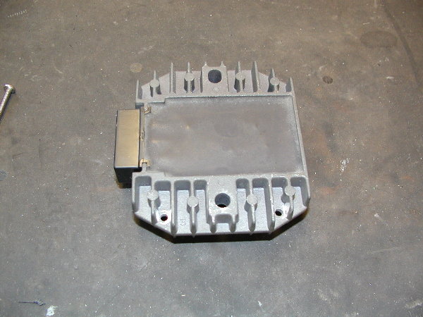
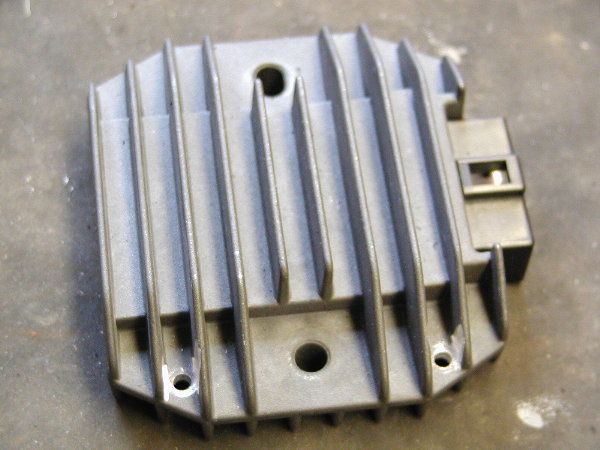
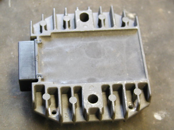
If you have had the opportunity to inspect a rectifier/regulator, you have probably noticed it is black, and it has fins. Both of these properties are to facilitate heat dissipation. The reason the rectifier/regulator needs to dissipate a lot of heat is because the regulator must convert whatever voltage (and associated current) the stator creates, and the system does not use, into heat. Also, the current the electrical system normally draws through the rectifier/regulator creates heat. What this means then is either high engine speed or heavy system loading, or both, generates high levels of heat in the rectifier/regulator. Heat is the culprit most likely to cause the demise of the rectifier/regulator. I have heard of riders using very small electric fans to keep the rectifier/regulator cool. I dont know if this is successful, but intuitively I would guess that the increased current load on the rectifier/regulator from the addition of the fan is out-weighed by the cooling benefit. In other words, I would guess that it most likely helps.
A word of caution in regard to jump-starting your bike with a car; If you find it necessary to do so, do not have the car engine running! The reason for this is due to automotive charging system design. A condition known as load dump can create large voltage spikes that the bikes rectifier/regulator is not designed to withstand. These voltage spikes can destroy a rectifier/regulator immediately, or it can weaken it such that it fails later when stressed with extended periods of either high engine speed or heavy system loading, or both.
Please refer to R1 Charging System Part 2 (long) for the section on Batteries.
Sam's explanations on batteries in relation to the bike electrical charging system
This is a continuation of R1 Charging System Part 1 (long)
Batteries
Batteries are probably the one component of the electrical system that people feel the most comfortable with, and at the same time, are quite likely the most misunderstood.
Most modern motorcycles (including the R1) use whats known as a Maintenance Free (MF) battery. These batteries never need water added because water is never lost in the charging process. These batteries are conventional lead-acid batteries (not gel) with rather large negative plates in comparison to the positive plates. Because of this, when the batteries are overcharged (overcharging is when conventional batteries lose water) the water is not broken down to it components of hydrogen and oxygen. Only oxygen is given off by the charge-saturated positive plates, then reabsorbed, hence no water loss. This process is known as the oxygen cycle.
A fully charged, brand-new battery will read a no-load terminal voltage of about 13.5 volts. The no-load terminal voltage of a battery is a good indication of its charge level, but taken at face-value, not of its potential total energy capacity. One way to determine a batterys health is to subject to a loaded test, such as attachment to a high current discharge tester. If this is not available, the home mechanic can perform a test utilizing the no-load terminal voltage. The battery is to be placed on charge overnight, it is then disconnected from the charger and allowed to stand for approximately ½ hour. The reason the battery is allowed to sit for ½ hour after removal from the charging voltage is to allow enough time for the surface charge to dissipate. If you were to measure the battery voltage immediately after disconnection from the charging voltage, you would find that the batterys no-load terminal voltage would match that of the charging voltage, and thus give you a false indication of charge level. Next, a digital voltmeter is used to measure the no-load terminal voltage. This terminal voltage now has the capability to determine total energy capacity due to the recent charge. In general:
13.5~13.2, brand-new fully charged
13.1~12.8, good used battery fully charged
12.7~12.5, marginal battery, still OK, but may leave you stranded
12.4 or less, may be sulphated or may have to be replaced.
Note: These values are for a battery at room temperature
Lead-acid batteries are charged, in system, with a voltage that is about 1 volt above their fully charged no-load terminal voltage. Looking at the chart above, that would say then the system charging voltage should be somewhere between 13.8~14.5 volts. You will find that if your charging system is operating properly, the system voltage, with the engine running, will fall somewhere inside these values. If the system voltage is outside of these bracketed values the battery will either discharge and sulphate if the voltage is below this, or burn up if the voltage is above.
Sulphation is a natural process that occurs as a battery discharges. Whenever current is pulled out of a battery, the sulphation process begins; it is the natural by-product of the chemical reaction that creates current flow. If the sulphation process is not allowed to continue, the battery is easily re-charged and the sulphation process is reversed. On the other hand, if allowed to continue, the battery becomes so sulphated it can no longer perform as it should. MF batteries are particularly susceptible to sulphation, which is why they should be kept topped off in regard to charge level.
Sulphation is the process in which lead sulphate crystals form on the battery plates, blocking the chemical process by which current is produced. Under normal charge/discharge cycles of the battery, these crystals are very fine and easily broken down upon recharge. If battery discharge is allowed to continue the lead sulphate crystals grow to such a size that the chemical process by which current is produced is essentially blocked, and subsequently, attempts to recharge the battery fail due to the overwhelming size of the crystals. If the battery is not soon rescued, the lead sulphate crystal growth will eventually internally short the plates and the battery will never recover. Heavily sulphated batteries can sometimes be brought back to life by shocking the plates. This is done by applying a higher than normal DC charging voltage to the battery. The higher voltage goes to work on the larger than normal lead sulphates crystals and sometimes can break them down so that normal charging can begin. If this technique is attempted, you must be sure to constantly monitor the charge current and as soon as the current begins to rise, the charging voltage must be immediately reduced so as to not overcharge the battery.
Batteries naturally self-discharge, which means even if a battery is not being used, the sulphation process continues unabated. A general rule of thumb is that a battery loses about 1% of charge capacity per day if left to self-discharge. This means that if you allow your MF battery to sit for extended periods of time without a precisely controlled charging current (about 1% of capacity per day) applied, it will not take too many weeks/months for the battery to sulphate and go bad.
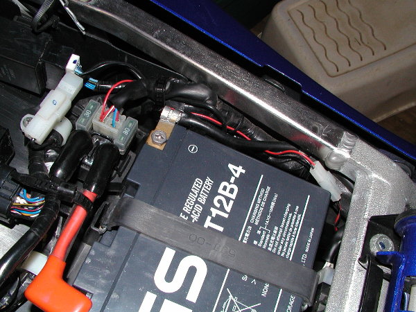
Battery charging capacity and charge rate can be easily determined with a couple of simple formulae. A batterys capacity is rated in ampere-hours (Ah). The R1 battery is rated at 10 Ah. To determine charging Ah, you multiply the rated Ah by 1.3, so for the R1, the charging Ah is 10 Ah*1.3 = 13 Ah. A common charging current level used is about 1/10 of the batterys rated Ah, so for our R1 example 10 Ah * 1/10 = 1 amp. To determine total charge time we divide the calculated charging Ah by the calculated charging current, in our example, this would be 13 Ah / 1 A = 13 hours. Keep in mind this is a calculation based upon a completely discharged battery, so this figure is a maximum.
Now a word about battery chargers; all battery chargers are not created equal!
The ideal battery charger would:
1) Sense if the battery is heavily sulphated, and if so, increase the charge voltage sufficiently high so as to break down the lead sulphate crystals and return to a normal charge voltage when appropriate.
2) Charge the battery at a voltage level that quickly charges the battery without overheating it.
3) Sense when the battery is fully charged, then throttle down the current so as to only replace the 1% of capacity per day loss associated with self-discharge.
What I have just described is exactly what a smart battery charger does. There are many on the market today and I highly recommend their use. These are especially nice if you do not have the time or inclination to try and diagnose what is wrong with your battery and what charging voltage/technique to use to recharge it. You can connect your battery all winter long to a smart charger without ever having to worry about over-charging it.
A word of caution: do not assume you can take a conventional 2 amp battery charger or a 1 amp wall-outlet-covering brick type battery charger and connect it continuously to your battery over winter storage to keep it charged. If you do so, you will end up with one big cooked paperweight for a battery. These chargers work fine for charging your battery overnight, but not any longer than 24 hours maximum, otherwise you will overcharge the battery and quickly cook it.
This reminds me of the time I spoke to an older gentlemen over the phone that told me he left his battery in his bike in his un-heated garage all winter long in St. Paul Minnesota, where winter is almost six months long and temperatures dip to 25 F. He said he simply connected up a 2 amp charger and left it connected all winter. As I was about to ask him how long he had been doing this, he said he has been using this technique for almost 20 years! I didnt know what to say. He then filled me in on his secret. He plugs his battery charger into the light socket on his garage-door opener. This way the battery gets, at a minimum, about two 5-minute shots of charge per day. Apparently this is sufficient charge to compensate for the self-discharge loss per day at those reduced temperatures. I thought How ingenious. Something so simple, yet it does the job so well.
I love simple, eloquent solutions to problems. (YEAH RIGHT!-martin)
Well, that pretty much wraps this up. There is still more detail and information I excluded for the purpose of brevity. I hope this answers a lot of the question people have and hopefully reduce some of the problems owners are having withtheir charging systems.Sam`s final verdict on RR
Even if you have not had problems with your charging system rectifier/regulator, and are an R1 owner, I would suggest taking a few minutes and read on .
Rectifier/regulators (R/R) are finned and black so as to optimize heat dissipation. HEAT is the number one killer of these components; followed by voltage transients (spikes). In most applications, R/Rs are mounted to the frame/chassis so as to use the thermal conductivity of the frame/chassis to help pull heat out of the R/R. In the R1, there is NO mechanical, therefore, NO thermal connection to the frame. This then makes the R/R in the R1 VERY susceptible to over-heating and eventual failure.
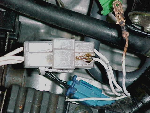
I believe the reason the R1 has been plagued with R/R connector problems is an issue of heat, initially, then followed by localized heating due to I*I*R drop (I*I*R = power). Here is my interpretation as to what is happening.
A common failure of the connector has been a fried contact to the red wire, which is the regulator positive (+) output. The failure of the contact cannot be due to excessive current alone. The reason I say this is because whatever current flows through the R/R red wire, must also flow through the black. Quite often the black-wire contact exhibits no excessive heating. In the case where both contacts on red and black wires show evidence of excessive heating, this then is evidence of excessive current flow through the R/R, and its destruction by. you guessed it, excessive heat.
In the cases where only the R/R red wire contact is destroyed, I believe this is due to excessive heat conducted out the red-wire contact. Quite often in electronic power circuits, the electronic component that controls the output current is mechanically and (of course) electrically connected to the output contact. In the case of the R/R, it is this component which transmits the largest portion of the total R/R heat to the R/R shell. If the shell cannot dissipate the heat quickly enough (such as NOT being connected to the chassis/frame), the internal electronic output device heats up and therefore so does the connector contact. I believe it is the excessive heat on the output contact that facilitates/accelerates any potential contact corrosion. Heat accelerates chemical reactions, and oxidation certainly falls into that category. Once oxidation begins, contact corrosion follows. With contact corrosion comes increased contact electrical resistance. With increased resistance comes increased power-drop and with more power-drop comes more heat. The summation of regulator heat and I*I*R (power)-drop, heats the contact to the point the connector plastic melts and the contact eventually corrodes to the point it can no longer flow the necessary current to the rest of the electrical system. When this occurs, the charging system fails to run the bike and, of course, charge the battery.
I also believe that if the R/R has gotten hot enough to accelerate the corrosion of the connector contact, if the R/R hasnt failed yet, its just a matter of time before it does.
At this point, I would also like to add that I believe stator coil connector (three contact, white housing) contact heating is a straight-forward problem of contact corrosion accelerated by I*I*R (power)-drop heating. A fix for this is either replacement of the connector/contacts, or the abrasion of the corroded contact(s) with medium/fine sandpaper and flush with aerosol contact cleaner. Coat ALL stator coil connector contacts with silicone dielectric grease.
So, what choices do we have so as to improve the reliability of the R/R, and subsequently, its connector? Well, obviously, the clear fix is to keep it cool.
Some cultural choices are:
1) Minimize the load on the R/R, which means no 100-watt headlamps, heated clothing, etc.
2) Minimize time spent at high engine rpms.
3) Minimize stop & go traffic situations; choose routes that may be longer, but keep the bike moving so as to optimize airflow past the R/R.
Some mechanical choices are:
1) Either replace or abrade corroded R/R contact(s) with medium/fine sandpaper and flush with aerosol contact cleaner. Coat ALL R/R connector contacts with silicone dielectric grease.
2) Re-mount the R/R to either the subframe or chassis so as to facilitate better heat transfer/dissipation.
3) Mount a small 12VDC fan atop the R/R.
I believe for the majority of owners, simply observing some cultural changes and the cleaning and application of silicone dielectric grease to the R/R connector will suffice. Surely, taking the time to re-mount the R/R would be time well spent.
For those that have had chronic R/R problems, I would clean/grease the connector, re-mount the R/R, and seriously consider the addition of a fan.
Sam's explanations on rectifier/regulator behavior under load
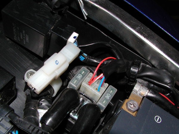
The plug melting is due to excess heat; nothing new there, right? This can be due to either
excessive current or an increase in resistance, or both. The power (heat) dissipated by the
contacts in the connector is a function of both current through them and their resistance.
Power equals the current squared, multiplied by the resistance. What this means is,
for example, if the contacts become slightly corroded and let's say the contact resistance
increases from 1 to 10 ohms, the power (heat) will increase almost 10 times.
The reason it 'almost' increases 10 times is because as the resistance increased,
the current will decrease slightly. Another example is, let's say, because of additional
electrical load on the system due to some new electronic gadgets (not Martin!! ;o)
and also maybe an new electric vest, the electrical system average current load has tripled.
Well, the heat at the contacts will then increase 9 times (!!) because power (heat)
increases with the square of the current. If both happen together (increased system current
load and contact corrosion), and using the values I gave in the above examples,
the heat at the contacts could then increase 90 times!!

This is why, most commonly, problems arise at the rectifier/regulator
and stator coil connectors. Your best defense here is to abrade the contacts
so they become nice and shiny. Clean them with a non-residual electrical cleaner
(non-lube type), and coat the contacts with silicone dielectric grease and re-connect.
Also, keeping your electrical system load as low as possible will help immensely.
Sam Farris.
Guide to trouble-shooting your electrical charging system
- First of all. fully charge the battery. If the battery is not healthy AND fully charged, you are likely to get unpredictable results using this fault-finding chart. You could just replace it with a battery off another motorcycle that has a good functioning charging-system. Using an acid-meter, verify that the battery is still healthy. If you haven't got one, any garage can do this for you.
- Use an accurate digital multi-meter. The $15 filler station variety will not do, but if you know anything about electrics, that's old news for you.
- Throughout this procedure, the abbreviation RR is used to designate Regulator-Rectifier because it's a tongue-twisting long term. All diagnoses are against a yellow background.
START |
| Switch the multi-meter to DC Volts. Switch the range to 20 or 50 V. Connect the multi-meter leads to the battery terminals. Start and rev the engine up to 2500 rpm. Check the battery-voltage | Higher than 13.5 V |
Rev the engine up to 5000 rpm. Check the reading on the meter. |
Lower than |
Charging system perfectly OK. You could still disconnect most of the connections on the bike and spray them with contact cleaner or WD40. This could prevent problems in the future. |
| Lower than 13.5
V |
Higher than 14.8
V |
| Let the engine idle, and connect the black multi-meter lead to the battery(+). Connect the red multi-meter lead to the RED output wire of the RR. Leave the RR connected to the bike. Check the reading on the meter. Leave the engine idling! | more than 0.2 V |
Bad connection in the positive lead from RR to battery(+). Check the entire lead (suspect the connectors as well as the fuse-box and fuses). Good connections are extremely important in this high current lead. Solve the problem and return to START |
| Less than 0.2 V |
||
| Connect the red multi-meter lead up to the battery's negative pole (-) Connect the black multi-meter lead up to the negative output of the RR (BLACK), but leave the RR connected up to its leads on the bike. If you can't find a negative output wire, then the casing of the RR is normally the negative lead to the frame. Check the reading on the meter. Leave the engine idling ! | more than 0.2 V |
Bad connection in the negative lead from RR to battery(-). Check the whole lead to the battery(-). If the RR doesn't have an output lead but uses the case as connection to the frame, clean the area where it is bolted and use new screws. Also check the connection between battery(-) and frame. Also suspect the plate on which the RR is mounted (sometimes it is rubber mounted and uses an extra cable from this plate to the battery(-) or frame). Disconnect all suspect terminals and clean. Best solution: connect the RR straight up to the battery(-) with an extra lead. Solve the problem and return to START |
| Less than 0.2 V |
| Test
Phase B |
|
Stop the engine. Disconnect the wires emerging from the stator. Switch the multi-meter to Ohms, the lowest range on the meter. Connect the multi-meter leads BETWEEN two of the three white wires. Check the reading on the meter. Switch one of the multi-meter leads to another of the three wires and check the reading again. Switch the other multi-meter lead to another of the three wires, and check the reading again. So, you need to take three readings. |
One of the readings is lower than 0.5 Ohms
or higher than 2 Ohms |
Bad
News.
Stator is at fault. Replace the stator and return to START |
All readings are within
0.5 to 2.0 Ohms |
||
Connect one of the multi-meter leads to one of the three white wires. Connect the other multi-meter lead up to the engine casing. Check the reading on the meter. Make sure the connection to the casing is a good one ! |
any reading between 100 Ohms and zero Ohms |
|
Infinite resistance (no
reading at all, or OL in the display) |
||
Switch the multi-meter to AC-Voltage (Range at least to 100 VAC). Make sure you DON'T switch it to DC-Voltage (=DC-Voltage or VDC). Connect the multi-meter leads between two of the three white wires emerging from the stator. Start the engine and rev it up to approx. 5000rpm. Check the reading on the meter. Switch one of the multi-meter leads to another one of the three white wires and check the reading again. Connect the other multi-meter lead to another one of the three white wires, and check the reading again. |
The three readings are
not equal, or one of them is below 60 Volts (AC) |
|
Three equal readings, all
higher than 60 Volts (AC) |
Test
Phase |
Disconnect the RR from the bike. Switch the multi-meter to the diode test position. Connect the RED multi-meter lead to the RED positive output wire of the RR. Connect the BLACK multi-meter lead to one of the white wires. Check the reading. Repeat this procedure for the two other white wires. |
You have a reading
of 1.00 V or lower on one of the three tests. |
Different Bad News. Regulator/rectifier is at fault. Replace it and return to START |
You have a reading
of 1.5 V or higher on all three tests |
||
Connect the BLACK multi-meter lead to the RED output wire of the RR. Connect the RED multi-meter lead to one white wire. Check the reading. Repeat this procedure for the two other white wires. |
You have a reading
below 0.2 V or above 1.0 V on one of the three tests |
|
You have a reading
of around 0.50 V on all three tests |
||
Connect the BLACK multi-meter lead to the negative output wire (BLACK) of the RR . If there is no output wire, connect the black multi-meter lead to the RR-case Connect the RED multi-meter lead to one yellow wire. Check the reading. Repeat this procedure for the two other white wires. |
You have a
reading of 1.00 V or lower on one of the three tests. |
|
You have a reading
of 1.5 V or higher on all three tests |
||
Connect the RED multi-meter lead to the negative output wire (BLACK) of the RR. If there is no output wire, connect the black multi-meter lead to the RR case Connect the BLACK multi-meter lead to one white wire. Check the reading. Repeat this procedure for the two other white wires. |
You have a reading
below 0.2 V or above |
|
You have a reading
on the display around 0.50 V on all three tests |
||
| As this was the last test, the only thing that can be at fault is the battery itself. Replace it with a healthy, fully charged one and return to START. | ||
![]()
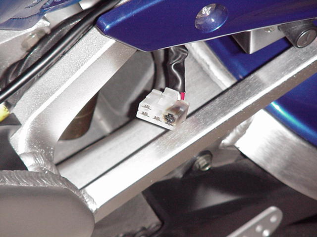
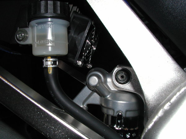
How to install a fan on the rectifier/regulator for better cooling
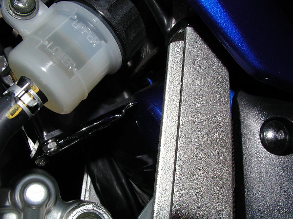
It is no secret that since the R/R is bolted to the plastic undertray, it is suffering from lack of cooling;
It should have been bolted to the frame to get a heat-sinking effect...now why Yamaha decide to bolt it on
plastic is beyond me...and those that are running aftermarket electric/electronic gizmos on their bikes
know what that mean...a burnt R/R and main wiring plug...bad things I'd say.
So here's Glenn on mounting a fan to it with pics!
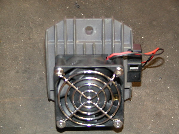
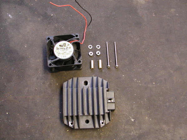
Here's how I mounted a cooling fan on my regulator:
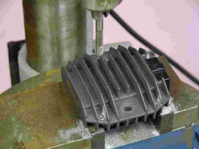
1. Remove regulator
2. Drill two 5/32" holes in the lower part of the regulator. Drill as far down
as possible but to still leave some material. The fan is a tight fit and needs
to be mounted as far down as possible due to possible contact with the tank.
3. I took a 1/4" burr and removed some material out around the holes on both
sides to compensate for the mounting screw head and spacer.
4. Install (2) 6-32 x 2" screws. The heads should be located on the backside
of the R/R.
5. Install spacers and 6-32 flat washers (1 per screw). The spacer is .600"
long and .25 OD. I used a 5mm brass carb sync tube that I cut with a tubing
cutting. The spacer can not be longer than .600 or you will not be able to put
the nut on the screw. The flat is used to increase the surface contact area
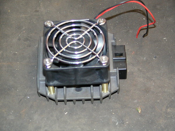
on the plastic fan.
6. Install 12 VDC fan 1.96"sq x 1"wide (airflow towards regulator) and use a
dab of blue Locktite on the nut. Tighten gently. I used a 30 cfm fan. Note:
Mount fan so that the 2 wires are up and to the right as looking at the R/R.
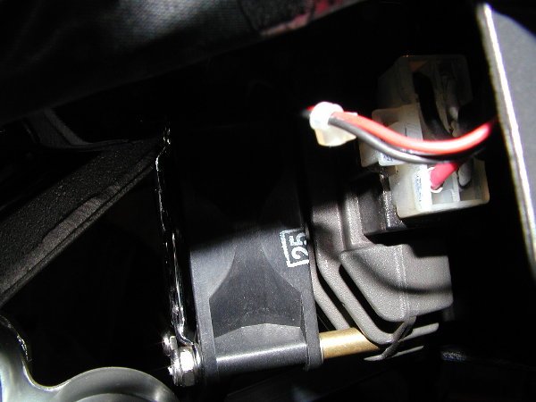
7. Reinstall R/R fan assembly on bike. I had to cut a 10mm wrench in half and
used the box end to tighten the lower bolt because the fan is now in the way.
8. Route wires to a keyed 12 volt source and suitable ground, I soldered the
wires to the 12 ga ground wire that attaches the the battery and soldered the
red wire to the connector as shown. I installed a male/female connector about
6" from the R/R fan just in case I wanted to remove the regulator.
9. Fan will now run while the key is on. Check for airflow by putting your hand
underneath the regulator.
Glenn